Add Hardware Integration
ONE WARE Studio is a comprehensive development environment designed for hardware and software integration. It features a system that allows you to add any FPGA development board using JSON configuration files. This is useful for configuring the graphical user interface (GUI) and ensuring that your toolchain supports your hardware.
Directory Structure
ONE WARE Studio organizes its files in a structured manner to facilitate easy management and integration of hardware components. Here is an overview of the directory structure:
First, let's have a look at the OneWareStudio folder inside your home directory.
The directory structure within ONE WARE Studio looks similar to this:
OneWareStudio
├── Packages
│   ├── Hardware
│       ├── Local
|           ├── FPGA
|           ├── Extensions
|               ├── PMOD
|               ├── CRUVI_LS
|               ├── CRUVI_HS
│       ├── OneWare.MAX1000
|           ├── FPGA
|               ├── MAX1000
|                   ├── fpga.json
|                   ├── gui.json
...
Local is the default package name where you can add your own hardware components. However, it's also possible to create a new directory for your own hardware package. This is useful if you want to sync your hardware integration with Git. Just ensure that the paths within your package follow the same structure as in Local.
- FPGA Boards are located inside
Packages/Hardware/<PACKAGENAME>/FPGA/<YOUR_FPGA_BOARD_NAME>. - Extension Boards are located inside
Packages/Hardware/<PACKAGENAME>/Extensions/<CONNECTOR>/<YOUR_EXTENSION_BOARD_NAME>.
Adding an FPGA Board
- Create a folder inside
Packages/Hardware/Local/FPGA/<YOUR_BOARD_NAME>. - Inside this folder, create a file named
fpga.json.
In that file you can add the pins of your board, the properties needed to compile for it and interfaces that are used for extensions or autoconnect.
To see how this file can look like when finished, you can have a look at the fpga.json for the MAX1000
The basic file structure for the fpga.json looks like this.
{
  "properties": {
    "quartusToolchainFamily": "MAX 10",
    ...
  },
  "pins": [
    {
      "description": "CLK",
      "name": "H6"
    },
    ...
  ],
  "interfaces": [
    {
      "name": "CLK",
      "pins": [
        {
          "name": "1",
          "pin": "35"
        }
      ]
    },
    ...
  ]
}
Properties
Valid properties at the moment are for compiling using Yosys and/or Quartus. These follow the documentation for the respective tools and control how the arguments are set for running the commands needed to compile/program the hardware.
This is an example that is valid for the Icebreaker V1.0 using OSS CAD Suite
"properties": {
    "yosysToolchainYosysSynthTool": "synth_ice40",
    "yosysToolchainYosysFlags": "",
    "yosysToolchainNextPnrTool": "nextpnr-ice40",
    "yosysToolchainNextPnrFlags": "--package sg48 --up5k",
    "yosysToolchainPackTool": "icepack",
    "yosysToolchainPackFlags": "",
    "openFpgaLoaderBoard": "ice40_generic",
    "openFpgaLoaderShortTermFlags": "",
    "openFpgaLoaderLongTermFlags": ""
  }
This is an example that is valid for the MAX1000 using Quartus
 "properties": {
    "quartusToolchainFamily": "MAX 10",
    "quartusToolchainDevice": "10M08SAU169C8G",
    "quartusProgrammerShortTermMode": "JTAG",
    "quartusProgrammerShortTermOperation": "P",
    "quartusProgrammerLongTermMode": "JTAG",
    "quartusProgrammerLongTermFormat": "POF",
    "quartusProgrammerLongTermOperation": "P"
  }
Pins
Pins are a simple array of JSON objects that look like this:
{
  "description": "CLK",
  "name": "H6"
}
They simply set the pins that are available for your hardware, so you can connect them in the GUI.
Interfaces
Interfaces can be used to graphically connect extensions for your hardware.
This is how you would define the PMOD Interface for the MAX1000:
"interfaces": [
    {
      "name": "PMOD_1",
      "connector": "PMOD",
      "pins": [
        {
          "name": "1",
          "pin": "M3"
        },
        {
          "name": "2",
          "pin": "L3"
        },
        {
          "name": "3",
          "pin": "M2"
        },
        {
          "name": "4",
          "pin": "M1"
        },
        {
          "name": "5",
          "pin": "N3"
        },
        {
          "name": "6",
          "pin": "N2"
        },
        {
          "name": "7",
          "pin": "K2"
        },
        {
          "name": "8",
          "pin": "K1"
        }
      ]
    },
    ...
]
The pin value must point to a pin that is already defined in Pins, while the name value provides the respective name that extensions can use to know where the real pin is located.
Adding an FPGA Extension
To add an FPGA extension, follow these steps:
- Create a folder inside
Packages/Hardware/Local/Extensions/<CONNECTOR>/<YOUR_EXTENSION_NAME>. - Inside this folder, create a file named
extension.json.
In that file you can define the pins and interfaces for your extension.
Here is an example of what the extension.json might look like:
{
  "name": "MyExtension",
  "connector": "PMOD",
  "pins": [
    {
      "description": "TX",
      "name": "A1"
    },
    {
      "description": "RX",
      "name": "B1"
    }
  ],
  "interfaces": [
    {
      "name": "UART",
      "pins": [
        {
          "name": "TX",
          "pin": "A1"
        },
        {
          "name": "RX",
          "pin": "B1"
        }
      ]
    }
  ]
}
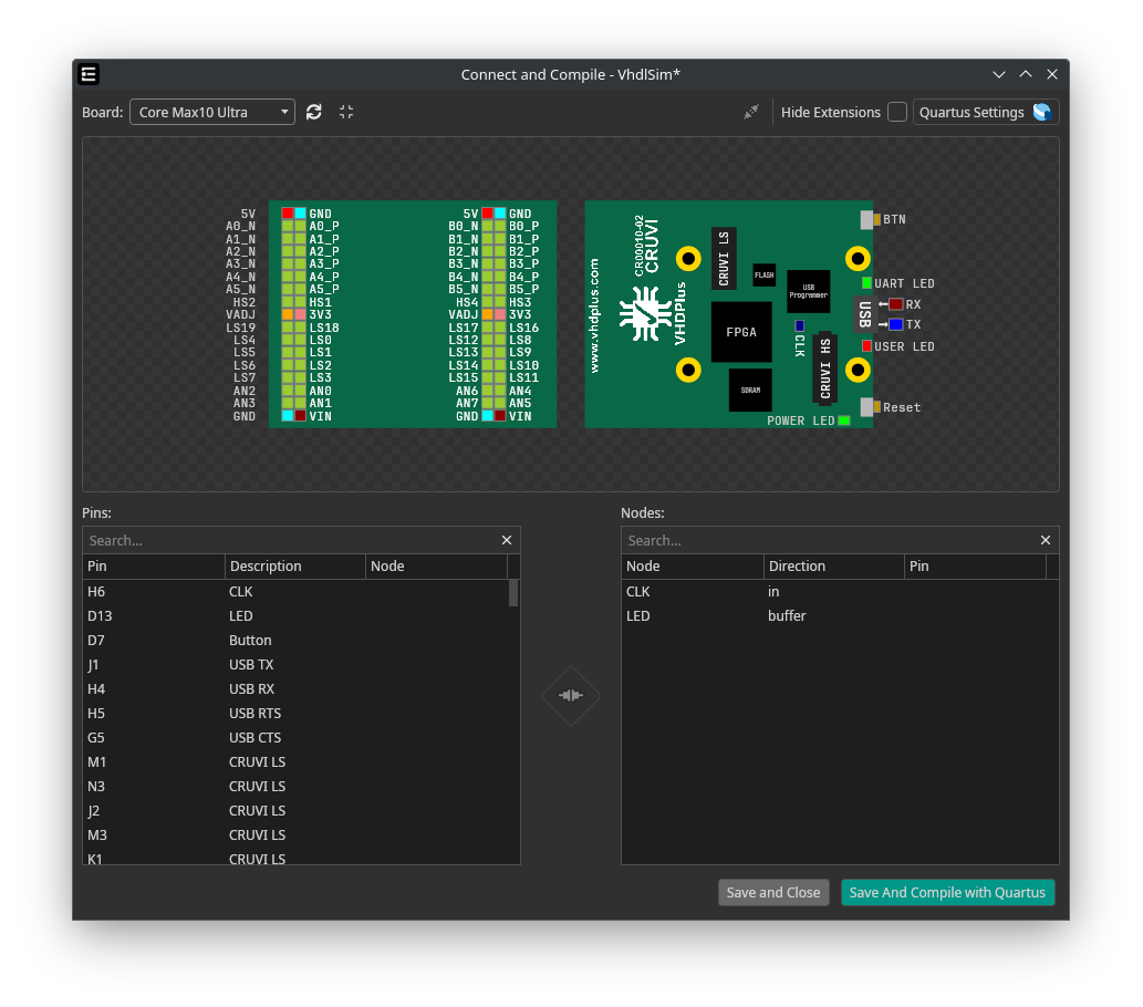
Adding a GUI
Adding a GUI is similar for both FPGA boards and extensions. Start by adding a gui.json file to your hardware folder (same location as fpga.json). A gui.json file consists of width, height, and an array of GUI elements like this:
{
  "width": 480,
  "height": 480,
  "elements": [
    {
      "type": "rect",
      "x": 40,
      "y": 40,
      "width": 400,
      "height": 400,
      "color": "#096845"
    },
    ...
  ]
}
The width and height can be calculated by multiplying the board size in millimeters by 4. For example, a board that is 100x100mm would have dimensions of 400x400px. It is recommended to use a border of 40px on each side, so you should set the width and height to 480x480.
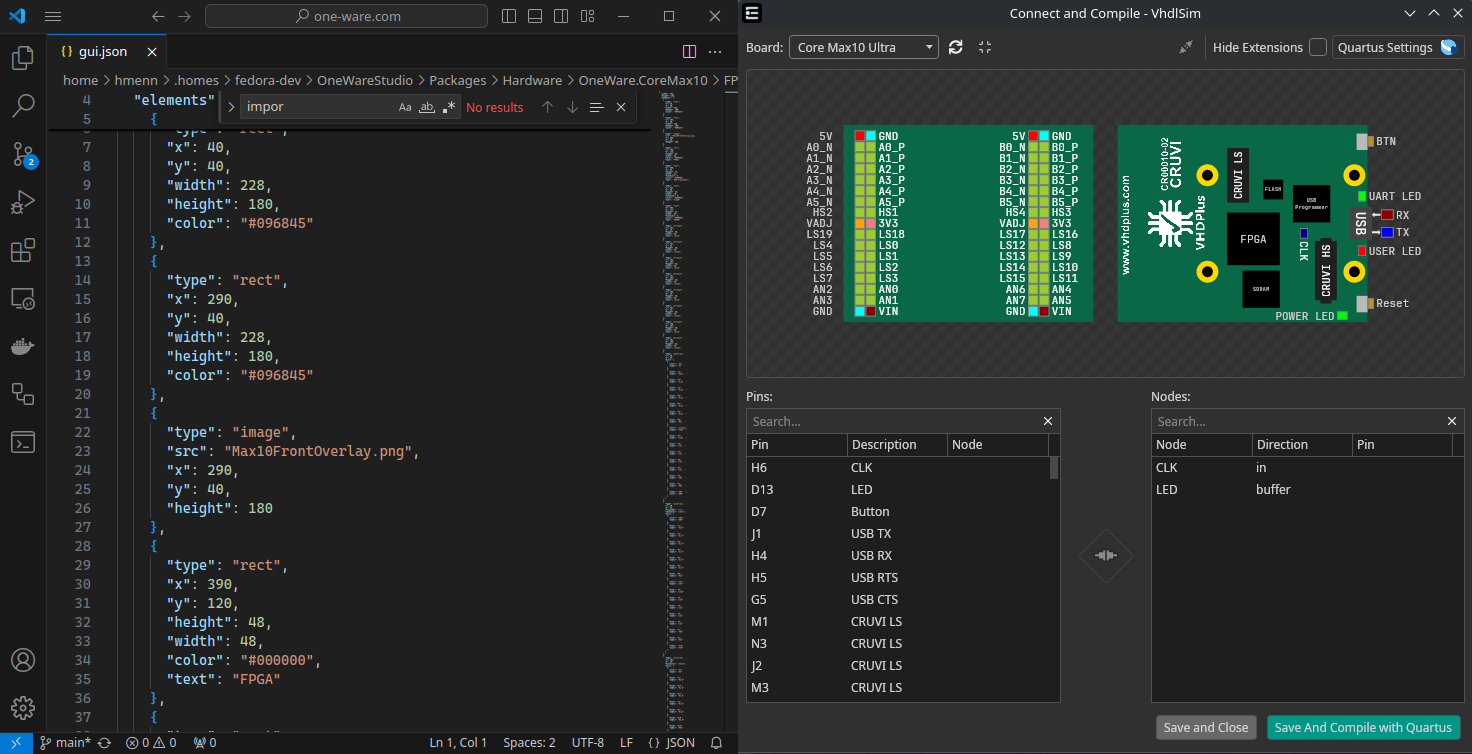
The IDE will show a live preview of your gui.json file!
Just open them next to each other, and view your changes on every save.
Here is a list of valid GUI Elements that can be added, including their possible attributes:
- The
textColorwill default to the IDE's default text color (white in darkmode / black in light mode). If you want to draw it on top of rectangles, you should choose a color with good contrast. - The
fontSizewill default to 10.
Rect
Creates a rectangle. This can be used as a background for the hardware.
| Property | Description | Type | Example | Required |
|---|---|---|---|---|
| x | X coordinate in px | double | 100 | ✅ |
| y | Y coordinate in px | double | 100 | ✅ |
| rotation | Angle to rotate in degree | double | 90 | |
| width | Width in px | double | 100 | ✅ |
| height | Height in px | double | 100 | ✅ |
| color | Background color | string | "#AA00BB" | ✅ |
| cornerRadius | CornerRadius | string | "10 15 20 10" | |
| boxShadow | Shadow for the element | string | "0 0 5 5 #77000000" | |
| text | Text to draw in the center | string | "Test" | |
| textColor | Text color as hex code | string | "#FFFFFF" | |
| fontWeight | Font weight | string | "bold" | |
| fontSize | Size for the text in pt | int | 10 |
Ellipse
Creates an ellipse.
| Property | Description | Type | Example | Required |
|---|---|---|---|---|
| x | X coordinate in px | double | 100 | ✅ |
| y | Y coordinate in px | double | 100 | ✅ |
| rotation | Angle to rotate in degree | double | 90 | |
| width | Width in px | double | 100 | ✅ |
| height | Height in px | double | 100 | ✅ |
| color | Background color | string | "#AA00BB" | ✅ |
Text
Creates a text. It is recommended to use the label property from Pin for labeling pins, or the text property from Rect for writing inside rects.
| Property | Description | Type | Example | Required |
|---|---|---|---|---|
| x | X coordinate in px | double | 100 | ✅ |
| y | Y coordinate in px | double | 100 | ✅ |
| rotation | Angle to rotate in degree | double | 90 | |
| color | Background color | string | "#AA00BB" | ✅ |
| text | Text to draw in the center | string | "Test" | |
| textColor | Text color as hex color code | string | "#FFFFFF" | |
| fontWeight | Font weight | string | "bold" | |
| fontSize | Size for the text in pt | int | 10 |
Image
Creates an image.
| Property | Description | Type | Example | Required |
|---|---|---|---|---|
| x | X coordinate in px | double | 100 | ✅ |
| y | Y coordinate in px | double | 100 | ✅ |
| rotation | Angle to rotate in degree | double | 90 | |
| width | Width in px | double | 100 | ✅ |
| height | Height in px | double | 100 | ✅ |
| src | Relative path to image | string | /Assets/overlay.png | ✅ |
Pin
Creates an interactive button, that can be used to graphically select a pin. The default width/height is 10px.
| Property | Description | Type | Example | Required |
|---|---|---|---|---|
| x | X coordinate in px | double | 100 | ✅ |
| y | Y coordinate in px | double | 100 | ✅ |
| rotation | Angle to rotate in degree | double | 90 | |
| width | Width in px | double | 100 | |
| height | Height in px | double | 100 | |
| color | Background color | string | "#AA00BB" | |
| bind | Pin to connect | string | "A4" | |
| label | Text to draw next to the pin | string | "A4" | |
| flipLabel | Show label on right side | boolean | true | |
| textColor | Label text color as hex code | string | "#FFFFFF" | |
| fontSize | Size for the label in pt | int | 10 |
PinArray
Creates an array of pins, which makes it easier to manage multiple pins next to each other.
| Property | Description | Type | Example | Required |
|---|---|---|---|---|
| x | X coordinate in px | double | 100 | ✅ |
| y | Y coordinate in px | double | 100 | ✅ |
| rotation | Angle to rotate in degree | double | 90 | |
| pinWidth | Default width for pins | double | 10 | |
| pinHeight | Default height for pins | double | 10 | |
| horizontal | If the pinArray is horizontal | boolean | true | |
| flipLabel | Show label on right side | boolean | true | |
| color | Default background for all pins | string | "#AA00BB" | |
| textColor | Default label text color as hex code | string | "#FFFFFF" | |
| pins | Included Pins | Pin[] | View below | ✅ |
Example for a horizontal pinArray:
{
  "type": "pinArray",
  "x": 80,
  "y": 168,
  "horizontal": true,
  "textColor": "white",
  "pins": [
    {
      "bind": "39",
      "label": "LED_R",
      "color": "red"
    },
    {
      "bind": "41",
      "label": "LED_B",
      "color": "blue"
    },
    {
      "color": "GND",
      "label": "GND"
    },
    {
      "color": "3V3",
      "label": "3V3"
    }
  ]
}
PinBlock
Similar to PinArray, but requires a width. The labels will be shown inside the pins by default. The pins will wrap once the width is reached, making this control useful for displaying blocks of pins.
| Property | Description | Type | Example | Required |
|---|---|---|---|---|
| x | X coordinate in px | double | 100 | ✅ |
| y | Y coordinate in px | double | 100 | ✅ |
| width | Max Width per row before wrapping | double | 100 | ✅ |
| rotation | Angle to rotate in degree | double | 90 | |
| pinWidth | Default width for pins | double | 10 | |
| height | Default height for pins | double | 10 | |
| color | Default background for all pins | string | "#AA00BB" | |
| textColor | Default label text color as hex code | string | "#FFFFFF" | |
| pins | Included Pins | Pin[] | View below | ✅ |
Example for a pinBlock:
{
  "type": "pinBlock",
  "x": 80,
  "y": 168,
  "width": 80,
  "pinWidth": 20,
  "pinHeight": 20,
  "pins": [
    {
      "bind": "39",
      "label": "LED_R",
      "color": "red"
    },
    {
      "bind": "41",
      "label": "LED_B",
      "color": "blue"
    },
    {
      "bind": "GND",
      "label": "GND"
    },
    {
      "bind": "3V3",
      "label": "3V3"
    }
  ]
}
USB
Creates a USB control, that allows connecting RX and TX easily.
| Property | Description | Type | Example | Required |
|---|---|---|---|---|
| x | X coordinate in px | double | 100 | ✅ |
| y | Y coordinate in px | double | 100 | ✅ |
| rotation | Angle to rotate in degree | double | 90 | |
| txBind | Pin for TX | string | "B6" | ✅ |
| rxBind | Pin for RX | string | "A6" | ✅ |
| flipLabel | Show label on right side | boolean | true |
Gui
Shows another gui.json file as an element.
| Property | Description | Type | Example | Required |
|---|---|---|---|---|
| x | X coordinate in px | double | 100 | ✅ |
| y | Y coordinate in px | double | 100 | ✅ |
| rotation | Angle to rotate in degree | double | 90 | |
| src | Relative path to gui.json | string | ../B1/gui.json | ✅ |
PMOD
Adds a PMOD connector.
| Property | Description | Type | Example | Required |
|---|---|---|---|---|
| x | X coordinate in px | double | 100 | ✅ |
| y | Y coordinate in px | double | 100 | ✅ |
| rotation | Angle to rotate in degree | double | 90 | |
| bind | PMOD interface to connect | string | "PMOD_1" | ✅ |
| connectorStyle | Adds an option to make connector smaller | string | "compact" |
CruviLS
Adds a CruviLS connector.
| Property | Description | Type | Example | Required |
|---|---|---|---|---|
| x | X coordinate in px | double | 100 | ✅ |
| y | Y coordinate in px | double | 100 | ✅ |
| rotation | Angle to rotate in degree | double | 90 | |
| bind | CruviLS interface to connect | string | "CRUVI_LS_1" | ✅ |
CruviHS
Adds a CruviHS connector.
| Property | Description | Type | Example | Required |
|---|---|---|---|---|
| x | X coordinate in px | double | 100 | ✅ |
| y | Y coordinate in px | double | 100 | ✅ |
| rotation | Angle to rotate in degree | double | 90 | |
| bind | CruviHS interface to connect | string | "CRUVI_HS_1" | ✅ |
Example Integrations
Here are some example integrations that demonstrate how to add hardware components using ONE WARE Studio: